
Prepainted Aluminum Coil: How to Interpret Bend-Test Results
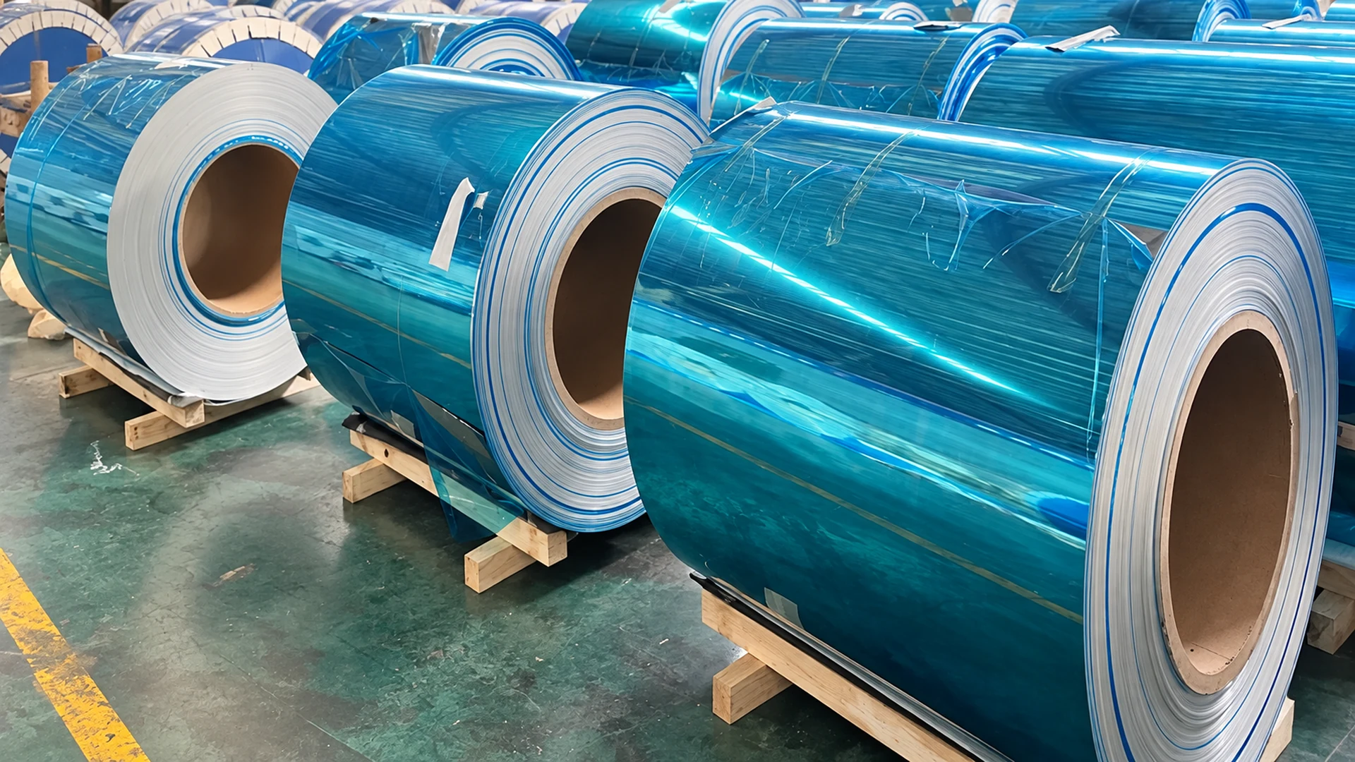
A bend-test result for prepainted aluminum coil is useful when the tested material, method and acceptance conditions are identified together. A rating such as 0T or 2T describes performance under a specified test; selecting material for a roof flashing, folded panel or roll-formed profile also requires checking the actual forming conditions. Read the report for both coating cracking and loss of adhesion, and establish whether the aluminum substrate remained intact. Compare alloy, temper, thickness, coating system, bend direction and specimen temperature before comparing ratings. When production behaves differently, preserve the damaged and unaffected samples, investigate the differences in material and processing, and validate a representative part before approving the material for that operation.
What Does a Bend-Test Result Actually Measure?
A coating bend test evaluates how the painted material responds to deformation. Its usefulness depends on recording what happened to the coating and the underlying metal.
Coating Cracking and Loss of Adhesion Are Different Outcomes
ASTM D4145-10(2022), Standard Test Method for Coating Flexibility of Prepainted Sheet, addresses the flexibility and adhesion of organic coatings on metal during bending. Its published scope explains that fabrication stresses can fracture the coating or cause it to lose adhesion to the substrate.
A crack interrupts the paint film. Loss of adhesion means that the coating has separated from a surface to which it was bonded. Both can occur on one bend, so a report should identify them separately. The word “pass” becomes useful only when the corresponding acceptance criteria are available.
For example, “2T, no cracking” records the crack observation at the stated test condition. It provides no adhesion result if adhesion was not evaluated. Conversely, “no loss of adhesion” does not, by itself, establish that the coating was free of fine cracks. Read each reported outcome against its own criterion.
With the same method, specimen configuration and test conditions, a lower T level represents a tighter bend. If 2T was the only bend tested, the result does not establish performance at 1T or 0T.
The European method EN 13523-7:2021 concerns resistance to cracking on bending. The European Coil Coating Association also identifies adhesion evaluation within the method’s scope. Reports should retain the method and version used; an ASTM result and an EN result should be compared through their stated procedures and criteria.
Why the Metal Substrate Must Remain Intact
ASTM D4145 requires a substrate capable of undergoing the test without fracture. If the aluminum splits, the result cannot establish coating flexibility independently of that damage.
Sherwin-Williams makes this limitation explicit for its PolyPREMIER coating: the product is not designed to bridge cracks in the substrate. That product-specific guidance reinforces the need to examine the metal beneath a damaged aluminum coil coating before attributing the failure to the paint.
Which Details Make Two Bend-Test Results Comparable?
Two ratings become comparable when they describe sufficiently similar specimens and test conditions. A different alloy, coating build or test temperature can change what the comparison means.
Match the Substrate and Coating System
Identify the alloy and temper, meaning the material condition resulting from mechanical or thermal processing. Record the base-metal thickness separately from coating thickness. “Polyester coated aluminum coil” identifies a coating family, but leaves the particular formulation, primer and coating build unspecified.
The National Coil Coating Association (NCCA) treats flexibility as a property of the substrate and coating combination. Sherwin-Williams’ PolyPREMIER data likewise identifies metal quality, thickness and cleaning or pretreatment as factors that can affect flexibility. The resin name alone is therefore insufficient to assign a bend-performance rating to a finished coated sheet.
Use the following fields when comparing a T-bend test report with another report or with a purchase specification:
| Report detail | What to compare |
|---|---|
| Specimen identity | Coil or batch reference, sample identification and the coated face tested |
| Base metal | Alloy, temper and metal thickness |
| Coating construction | Primer and topcoat identity, front/back differences and film thickness |
| Method | Standard, edition and any agreed departures from the procedure |
| Bend direction | Orientation of the bend axis relative to the rolling direction |
| Temperature | Specimen temperature during testing and the stated conditioning |
| Result | Rating, observed cracking, coating removal and the acceptance criteria |
Read the Conditions Behind the Rating
ASTM D4145 specifically identifies specimen temperature and bend direction as variables that should be agreed between supplier and user. “Room temperature” without a recorded condition offers less information than a documented specimen temperature.
When reviewing TOP METAL’s prepainted aluminum coil, connect any stated test result to the particular material configuration being considered. Treat an absent field as a question to resolve before drawing a comparison.
Why Can a Passing Test Differ from Production Forming?
A laboratory result represents its specimen and procedure. A production operation adds the geometry and contact conditions of the actual equipment. Differences between those conditions can explain why painted aluminum coil performs differently after forming.
Relate the Test Specimen to the Actual Bend and Tooling
A brake-formed flange, a rolled profile and a folded edge involve different forming sequences. At the outside of a bend, the coating must accommodate the stretching of the underlying metal while remaining bonded. Tool contact introduces a separate opportunity for surface damage. Review the inside radius, bend direction, tooling surfaces, clearances and material handling for the intended operation.
NCCA identifies rough dies, insufficient tooling clearance and poor alignment as sources of surface damage. Its processing guidance also points out that the coating contributes to the material’s total thickness. A setup used for bare sheet therefore deserves review when coated stock is introduced.
These checks matter when bending aluminum sheet without cracking is the production objective: paint damage may involve stretching, loss of adhesion, a scratched contact path or a crack in the metal itself. Recording where the damage first appears helps narrow the investigation.
Keep R/t Separate from a T-Bend Rating
The ratio R/t describes a geometric relationship: the part’s inside bend radius, R, divided by the base-metal thickness, t.
Hypothetical example: a sheet has a base-metal thickness of 0.50 mm, and the intended part has an inside bend radius of 1.00 mm. Its R/t = 1.00 ÷ 0.50 = 2.
This calculation does not establish a 2T test rating under ASTM D4145 or EN 13523-7. A T-bend rating comes from the specified test and its evaluation. The example also provides no recommended minimum radius for an alloy or coating. Its purpose is to keep the part drawing’s geometry separate from the coating-test result used to assess material suitability.
How Should Cracks, Peeling and Tool Marks Be Investigated?
Begin with the location and form of the damage, then compare the material and process evidence. “Cracking after bending” describes an observation; several mechanisms may need investigation.
Identify Where the Damage Occurs
Photograph the visible and reverse faces, mark the rolling direction, and identify the inner or outer bend surface. Retain damaged pieces together with unaffected material from the same coil, so subsequent checks remain traceable.
| Observation | Useful next evidence | Limit of the observation |
|---|---|---|
| Fine cracks in the paint at the bend | Coating continuity, metal condition, actual bend geometry and test conditions | A visible line alone does not identify a formulation or curing problem. |
| Peeling or lifted coating | Both separated surfaces, the layer where separation occurred and adhesion checks | Peeling alone does not prove that pretreatment caused the failure. |
| A split through the aluminum | Alloy, temper, thickness, edge condition and the forming sequence | Coating performance cannot be isolated from a fractured substrate. |
| Scratches or repeated contact marks | Corresponding tool surfaces, burrs, clearances and alignment | A tool mark alone does not establish inadequate coating flexibility. |
Compare Material Evidence with Process Evidence
An adhesion check on flat sheet establishes a baseline under that test condition. It does not show how the bond performs after a particular forming operation. Comparing identified flat and formed specimens can help establish whether a change in coating adhesion is associated with deformation.
If damage appears after a particular forming stage, inspect that stage and its contact surfaces. If behavior changes between coils, retain the batch identities and compare both material records and setup records.
Cure or pretreatment problems can be investigated when the evidence points in that direction. Establishing either requires relevant testing and process information; surface appearance alone is insufficient. Record a suspected cause separately from a confirmed finding.
How Do You Validate the Material for the Actual Part?
Material approval should connect the tested coil with a representative part made under the intended conditions. The result needs to be usable by both the person buying the material and the person setting up production.
For TOP METAL’s 3003 PE/PVDF coated aluminum coils, that discussion should identify the requested temper, thickness, coating construction and final bend geometry. A choice of PE or PVDF leaves those details to be established for the application.
Use Representative Material and the Intended Process
Agree which bends, edges and visible surfaces the trial must represent. Keep the trial material identifiable and record the forming equipment, direction and relevant settings. Inspect the part against the agreed appearance and adhesion requirements, with additional examination where the application calls for it.
A useful trial record includes:
- Material and sample identities linked to the selected specification.
- Coating system, coated face and available film-thickness information.
- Part drawing, critical bends, tooling and forming conditions.
- Observations of coating cracking, peeling, substrate damage and contact marks.
- Applicable acceptance criteria, photographs and the approval decision.
Retain the conditions alongside the result. When the substrate, coating configuration or production process changes, review whether the earlier trial still represents the new operation. The extent of further validation follows the application and customer requirements.
To discuss forming requirements with TOP METAL, provide the material specification, a drawing of the critical bend and the test or acceptance requirements.