
How Do You Read an Aluminum Bar Grating Load Table?
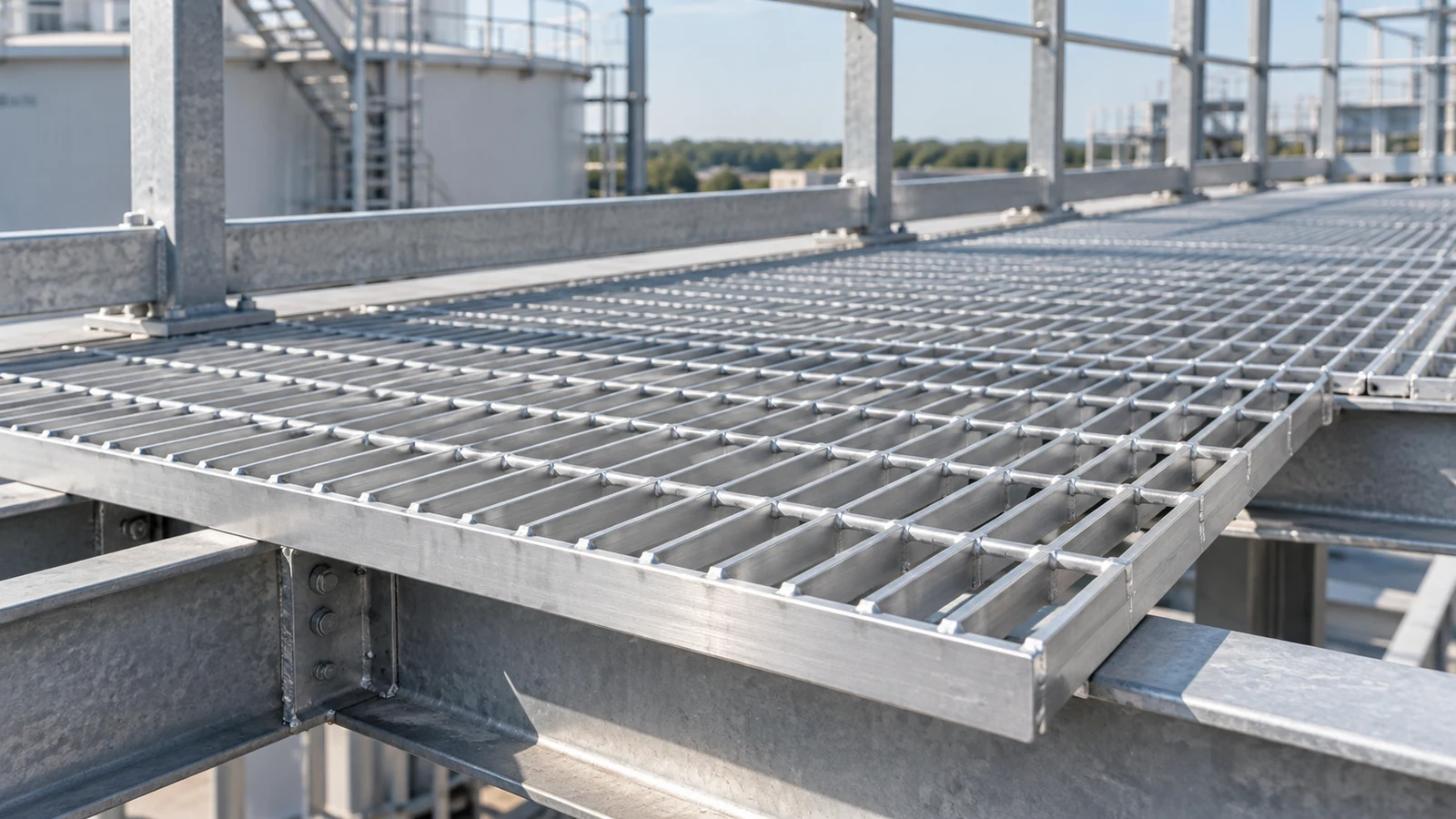
An aluminum bar grating load table is useful only when its product configuration, span, loading pattern and design assumptions match the panel being considered. Check the required load and the corresponding deflection separately: a demand below the tabulated load can still produce more movement than a project permits. A concentrated-load entry also does not automatically cover a wheel or a narrow equipment foot.
When evaluating TOP METAL’s custom aluminum walkway grating, connect the offered bar section, spacing and support drawing to the applicable load table. The examples below explain that reading process; they are not TOP METAL product ratings or project-specific structural approvals.
Match the Load Table to the Actual Grating and Span
Identify the grating family, bar section and spacing
Start with the table heading rather than its largest load value. A table for one grating family is not automatically transferable to another product with the same alloy or outside dimensions. Rectangular bearing bars and aluminum I-bar grating have different cross-sections; the relevant section properties, bar spacing and manufacturing configuration must be established before comparing capacity.
The bearing bars carry load across the span. Their depth and cross-sectional shape affect bending resistance and stiffness, while their spacing determines how many bars are available across a given width. Cross bars connect the assembly, but their presence does not make every direction or load footprint equivalent.
Match the table heading to the proposed panel
| Table information | What to establish | Common misreading |
|---|---|---|
| Product family and material basis | The listed construction, alloy/temper assumptions and design basis apply. | Any aluminum grating can use the same table. |
| Bearing-bar section | Depth, thickness and rectangular or shaped section match. | Equal overall depth means equal stiffness. |
| Bar spacing | The center-to-center spacing and its units match. | A spacing designation is necessarily a millimeter dimension. |
| Span and support model | The table’s unsupported span and support assumptions match the drawing. | Outside panel length is always the tabulated span. |
For example, Grating Pacific’s published “19 Space” aluminum table identifies a bearing-bar spacing of 1-3/16 in. The “19” is not 19 mm. Read the designation in that table’s own system rather than translating the number by appearance. [1]
Use the stated span definition, not the outside panel length
Locate the support lines and bearing-bar direction on the drawing. Where the table defines span as the clear unsupported distance, use that dimension—not the complete panel length including its supported ends. A panel turned through 90 degrees may retain the same outside dimensions while placing the bearing bars in the wrong direction for the intended support arrangement.
At this point, the decision is whether the table is applicable. If the drawing and table do not agree, resolve the mismatch before selecting a row or interpolating a value.
Read Uniform Load, Concentrated Load and Deflection as Different Quantities
Keep psf, pounds per foot of width and deflection separate
The letters in a load table describe different quantities, not interchangeable versions of a panel’s “weight limit.” In the inch-pound table used here, the legend distinguishes the following:
Read each value with its loading diagram and units
| Symbol | Meaning in the example table | Units |
|---|---|---|
| U | Uniformly distributed load over the grating area | lb/ft², commonly written psf |
| C | Concentrated load at midspan, expressed per foot of grating width | lb per linear foot of grating width |
| D | Deflection associated with the relevant U or C row | inches |
Keep the deflection paired with its loading case. The D row associated with a uniform load is not the deflection for the concentrated load underneath it. Metric tables may use different unit conventions, so compare definitions before converting numbers.
Check the loaded footprint before using a concentrated-load value
A tabulated midspan load expressed per foot of grating width does not automatically represent a small contact patch. A narrow equipment foot may initially load only part of the panel width. Its behavior depends on the bars engaged and how the assembly distributes that load. [2]
Do not multiply C by the entire panel width and use the result to approve an arbitrary wheel or equipment foot. Establish the footprint, position and applicable load case first. TOP METAL’s walkway and stair-tread specification guide covers the drawing and support information needed to describe the application before a table is selected.
Check Deflection Even When the Load Is Below the Table Value
Separate a load-capacity check from a deflection check
A strength-related load limit and a deflection limit answer different questions. The first concerns the table’s structural design basis; the second concerns how much the panel moves under a stated load. Read both against the project’s requirements instead of treating a capacity comparison as a complete acceptance decision.
Work through one clearly labeled reading example
Published reference data: Grating Pacific’s 19 Space aluminum table gives a uniform load of 281 psf and a corresponding deflection of 0.324 in for the 1 × 3/16 in rectangular bearing-bar entry at an unsupported span of 3 ft, approximately 914 mm. [1]
The table applies to the 19-series product configurations identified in its heading, with bearing bars on 1-3/16 in centers. Its theoretical values use the gross bearing-bar sections and a bending fiber stress of 12,000 psi. These are the reference table’s assumptions, not verified properties of a TOP METAL panel. Matching only the bar dimensions is therefore insufficient to transfer the table to another product.
Published table values and separate hypothetical project inputs
| Item | Value | Basis |
|---|---|---|
| Tabulated uniform load, U | 281 psf (13.45 kPa) | Published reference table |
| Corresponding deflection | 0.324 in (8.23 mm) | Published reference table |
| Total uniform load to evaluate | 250 psf (11.97 kPa) | Hypothetical input, including applicable load contributions |
| Deflection limit for this example | 0.25 in (6.35 mm) | Hypothetical project criterion, not a universal requirement |
Assume the same geometry, support arrangement and uniform loading pattern, with linear-elastic behavior. Deflection then scales with the load:
Estimated deflection = 0.324 × (250 ÷ 281) = 0.288 in, approximately 7.32 mm.
The demand of 250 psf is below 281 psf, but the estimated movement is above the assumed 0.25 in limit, approximately 6.35 mm. The numerical load comparison alone therefore does not establish acceptability.
Identify the controlling condition before selecting another size
The same relationship can be rearranged to find the uniform load corresponding to the hypothetical deflection limit:
Uniform load at the example’s deflection limit = 281 × (0.25 ÷ 0.324) ≈ 216.8 psf, approximately 10.38 kPa.
Under these assumptions, the deflection limit controls before the tabulated bending-stress limit. The 250 psf demand is below 281 psf but above the approximately 216.8 psf associated with the chosen movement limit. This calculated value is specific to the teaching example; it is not an additional manufacturer rating.
The next step is to have the responsible engineer evaluate a suitable bearing-bar section, support spacing or other permitted configuration change, then repeat both checks using the applicable data. Do not solve a deflection problem merely by choosing a different row with a higher headline load, or apply this load ratio to a different loading pattern.
The metric figures above are unit conversions of the same reference example. They do not make a nominal 25 × 5 mm bar interchangeable with a 1 × 3/16 in bar. A metric product must be checked against its own section dimensions and applicable load data.
Understand Why a Small Span Change Can Matter
Distinguish span effects from load scaling
Changing the load on the same panel is not the same operation as changing its span. For an unchanged section and material in a simply supported, uniformly loaded elastic model, the stress-controlled allowable uniform load varies with 1/L². At a fixed uniform load intensity, deflection varies with L⁴, where L is span.
A hypothetical 20% increase in span therefore gives:
Span increased to 1.20 times its original value; other model inputs unchanged
| Quantity | Ratio to the original value | Interpretation |
|---|---|---|
| Stress-controlled uniform-load capacity | 1 ÷ 1.20² ≈ 0.694 | About 69.4% of the original value |
| Deflection at the same uniform load intensity | 1.20⁴ ≈ 2.074 | About 207.4% of the original value |
Here, “same load intensity” means the same distributed load per unit area, not the same total force spread over a longer panel. Keeping that distinction explicit prevents another misleading comparison.
Do not extrapolate beyond the table without checking the model
These ratios explain sensitivity; they are not permission to extend a manufacturer’s table. Continuous spans, cantilevers, changed sections, concentrated loads and different support details require their own treatment. Other limits may govern before the simple bending relationship does.
When a layout changes after a quotation, give TOP METAL the revised support spacing and panel drawing rather than retaining the original product description with a longer overall dimension. The revised configuration needs a matching technical basis.
Recognize When the Published Table No Longer Applies
Read dead-load, surface and table-footnote conditions
Check whether the stated load includes self-weight or refers to loading added to the grating. The aluminum P-19 tables in ANSI/NAAMM MBG 531-24, printed pages 12–13, explicitly exclude the grating’s dead load. Identify how self-weight is accounted for in the project calculation; do not omit it or count it twice. [2]
Read heavy lines, shading and surface notes just as carefully. A highlighted span range may correspond to a particular pedestrian-load and deflection combination, not every load on the page. Surface-specific rules for serrated bars also belong to the source table; do not substitute a smooth-bar entry without checking the applicable instructions. [1]
Escalate modified panels and unmatched load cases for review
A cutout that interrupts bearing bars, a changed support location or an unmatched local load changes the load path. An intact-panel table does not demonstrate the adequacy of that modified arrangement. Resolve the structural detail with the responsible engineer and obtain documentation that corresponds to the actual supplied configuration. [2]
When considering an alternative from TOP METAL’s aluminum bar grating range, request the drawing and load–deflection information for that specific option. Compare it against the same span, loading footprint and acceptance criteria before making a commercial comparison.
The practical objective is a traceable match between panel, span, load case, deflection criterion and table notes. To discuss a proposed order with TOP METAL, submit the grating drawing and load-table requirements, including the support layout, loading footprint, required limits and the reference table being evaluated. Confirm which technical documents apply to the offered product before treating a published value as its rating.
Technical References
[1] Grating Pacific. 19 Space (1-3/16 in) Aluminum Grating Load Table, one-page reference sheet. Used for the spacing designation, U/C/D legend, 1 × 3/16 in entry at a 3 ft unsupported span, calculation basis and footnotes. Undated; accessed October 27, 2026.
[2] National Association of Architectural Metal Manufacturers. Metal Bar Grating Manual, ninth edition, ANSI/NAAMM MBG 531-24 (2024). Printed pages 12–13: aluminum P-19 load tables and notes; page 15: installation and modified bearing bars; Appendix A, page 27: loading diagrams.